No. 3, 19 Sayyad Shirazi St., Mashhad, Iran
051-38824146
Persian


Behso Niro Shargh company
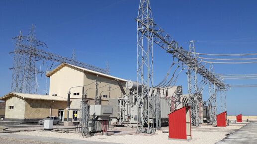
Metal structures in electrical substations form the main framework and are responsible for supporting and bearing the weight of heavy equipment (such as transformers, circuit breakers, disconnectors, busbars, and insulators). These structures must withstand static loads (equipment weight), dynamic loads (forces from short circuits, wind, and earthquakes), and weather conditions.
General Fabrication Stages of Metal Structures
The fabrication process generally includes the following stages:
General Fabrication Stages of Metal Structures
The fabrication process generally includes the following stages:
1. Design and Drafting:
Engineering Calculations:
Calculating applied loads, mechanical forces, and selecting appropriate steel profiles (channels, I-beams, square/rectangular tubes, angles) using specialized software like SAP2000, ETABS, STAAD.Pro,SOLIDWORKS, and ANSYS.
Preparation of Workshop (Fabrication) Drawings:
Creating detailed drawings for cutting, connections, and welding for the production workshop.
2. Cutting:
Steel plates and profiles are cut according to the fabrication drawings with high precision.
Cutting Methods:
Plasma Cutting: very common for cutting plates of various thicknesses with high precision and speed.
Oxy-Fuel Cutting: used for heavy sections.
Band Saw: for cutting long profiles.
Laser Cutting: for high-precision work (less common for large-scale substation structures).
3. Drilling:
Creating necessary holes for bolts and screws using industrial radial drills or CNC machines. Accuracy in the position and diameter of the holes is critical for the correct installation of equipment.
4. Bending:
Bending plates or profiles to create required forms (such as gusset plates) using a press brake.
5. Assembly and Welding:
Initial Assembly (Fit-Up): cut and drilled parts are temporarily assembled (e.g., with tack welds) to ensure dimensional accuracy and correct geometry.
Final Welding: this stage is the core of the fabrication process.
Common Welding Methods:
Shielded Metal Arc Welding (SMAW): for workshop and site welding.
Submerged Arc Welding (SAW): for long, straight seams with very high quality and speed (often used for main beams).
CO2 Welding (GMAW/FCAW): very common due to its speed and quality.
Weld quality: quality control of welds is performed through Visual Testing (VT), Magnetic Particle Testing (MT), Liquid Penetrant Testing (PT), and for critical welds, Ultrasonic Testing (UT) or Radiographic Testing (RT).
Welders must hold valid certificates according to recognized standards (such as AWS D1.1).
6. Surface Preparation and Painting:
Surface Cleaning (Sandblasting): the metal surface is thoroughly cleaned by projecting steel shot or abrasive sand to remove rust, grease, and any contaminants. This is essential for creating a rough surface (anchor profile) for better paint adhesion.
Painting:
Primer: immediately after sandblasting, a layer of anti-corrosion primer (epoxy or zinc-rich) is applied to prevent corrosion.
Topcoat: after the primer dries, one or two layers of a topcoat (often polyurethane) resistant to UV, moisture, and weather conditions are applied. The color is often light gray or green (standard substation colors).
The paint is typically applied using an airless spray method.
7. Transportation and Erection:
Structures are transported to the site as large modules or individual components.
On site, they are lifted into place by heavy-duty cranes and connected to the concrete foundation using High-Strength (HV) bolts.
The leveling and plumbness of the structure are carefully controlled.
Types of structures at different voltage levels:
A) High Voltage (HV/EHV) Substations:
Equipment support structures: these structures are very heavy and tall.
Transformer structure: designed to support transformers weighing several tens of tons. Often in the form of a strong steel platform.
Circuit breaker structure: for supporting air-blast or SF6 circuit breakers.
Disconnector structure: for installing disconnectors.
Busbar structures: for supporting main busbars and their insulator supports. These structures are usually in the form of gantries or towers.
Materials: heavy profiles (large rectangular tubes and channels, IPE, INP I-beams) are used. Welding is of very high quality and under strict control.
B) Medium Voltage (MV) Substations:
Structures are lighter and smaller.
Transformer structure: for smaller dry-type or oil-immersed transformers.
MV switchgear structure: for installing medium voltage cubicles.
Busbar structures: in smaller dimensions.
Materials: lighter sections such as medium-sized tubes, channels, and angles are used.
C) Low Voltage (LV) Substations:
Structures are generally pre-fabricated panelboards.
The body of the LV distribution panels itself acts as the structure.
These enclosures are typically made from galvanized sheets that are cut, bent, and riveted or screwed together.
Galvanizing replaces painting, providing a highly durable method of corrosion protection (cold or hot galvanizing).
For installing a large LV panel, a simple steel frame or rack might be used.
Construction of Civil Structures (Foundations and Concrete Structures)
These structures form the base for supporting the steel structures and equipment.
Design:
Foundation design is based on applied loads (dead and live) and soil type (based on geotechnical investigation), performed using civil engineering software.
Execution:
Excavation according to the foundation dimensions.
Formwork using wood or modular metal forms.
Reinforcement:
Placing networks of steel rebar inside the formwork. The location of the anchor bolts for the steel structure is set with millimeter precision within the formwork.
Concrete Pouring:
Pouring concrete of the designed grade ( C25 or C30). The concrete must be thoroughly vibrated to remove air pockets.
Curing: keeping the concrete moist for several days to achieve its ultimate strength.
Formwork is removed after sufficient strength is gained.
Types of Foundations in Substations:
Isolated footing: for individual structure legs.
Strip footing: for retaining walls or rows of equipment.
Mat foundation: for very heavy transformers or in soils with low bearing capacity.
Pile foundation: in very soft ground.
Final Summary
The fabrication of electrical substation structures is a combination of precision mechanical engineering (in metal fabrication), civil engineering (in foundation construction), and rigorous quality control testing. The choice of fabrication methods, welding, and painting directly impacts the lifespan, safety, and reliability of the entire substation.